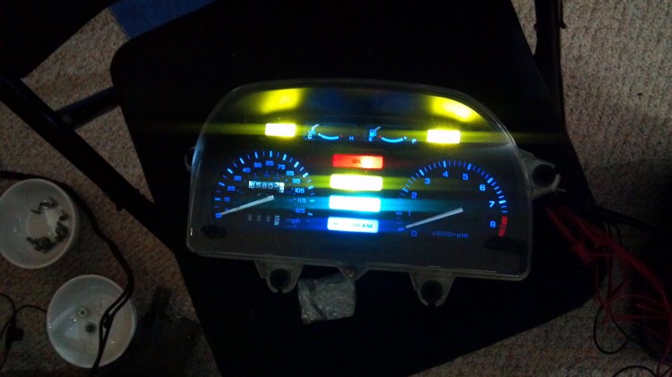
Over the course of the last few months I upgraded my PC800 from incandescent bulbs to 100% LED bulbs. Every single bulb down to the bulb in the Honda Marine Voltmeter has been changed out for an LED replacement. The full list of bulbs I purchased is available here. Above you can see all of the bulbs in the meter panel lit up. The bulbs I selected wash out the blue and green colors for the neutral and high beam lights but do well everywhere else. It’s not a big deal to me but some people might want to color match LEDs to the various lens colors.
I ended up replacing the self-cancel turn signal unit on my PC800 with some relays to disable self-cancel functionality. Eventually I want to build my own self-cancel unit either based upon an Arduino or done through circuit design. It might take a few months but I’ll eventually get full turn signal cancel functionality back. If you are doing an LED conversion, I would suggest bypassing your self-cancel unit so that you don’t let the magic smoke out. I made that mistake which is why I ended up having to bypass my (dead) self-cancel unit.
I also replaced the flasher relay in my PC800. Initially I built my own but then I found an off-the-shelf unit that I liked better. Unless you like building your own electronics, I would suggest buying the off-the-shelf unit. It is much simpler.
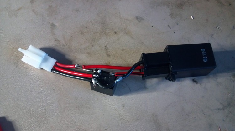
I modified the off-the-shelf flasher unit with a relay (seen above) to disconnect the load leg of the relay from the rest of the bike when I am not using the turn signals. This is to prevent leakage current/voltage from getting into the rest of the wiring harness and causing very dim but still visible lighting of the turn signal indicators even when they aren’t in use. The load lead is hooked to the Normally Open side of the relay. One side of the relay coil hooks to the +12 leg and the other hooks to the ground leg. Note that the ground leg goes to +12 when the flashers are not in use thus deactivating the relay. The diode that you can see above isn’t strictly necessary to the circuit but I decided to put it in anyway. It goes with the white stripe toward the ground side of the circuit. Easy!
This is a schematic drawing of the circuit that I used to disconnect the load leg of the relay. Yes, it’s a bit primitive of a drawing but you should be able to get the idea.
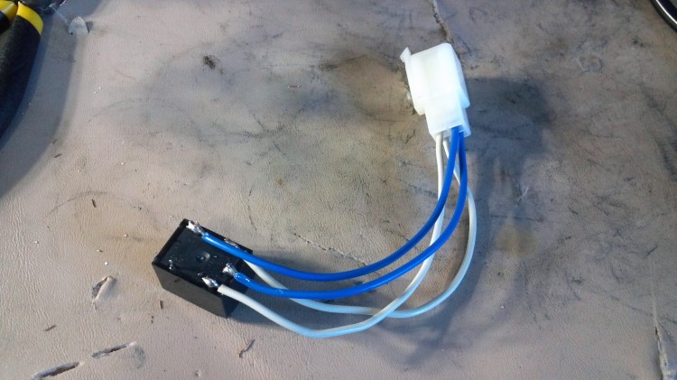
I also decided to replace the position light relay while I was at it. The two white wires go to the coil and the two blue wires go to the normally open part of the relay. There isn’t any reason to replace this relay but I decided to do it anyway. The Honda part number is P/N: 38601-MB3-671. Rather than pay $35-$45 for a replacement, you can build your own for under $15. If anyone wants ore details, I can look for the schematic I drew of this circuit and post pictures. Just leave a comment below and I will put it up.
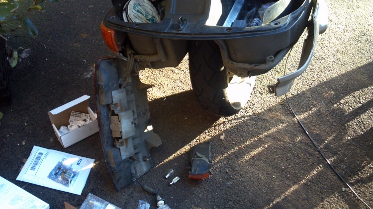
I swapped in the LED bulbs throughout the bike. They are very easy to install.
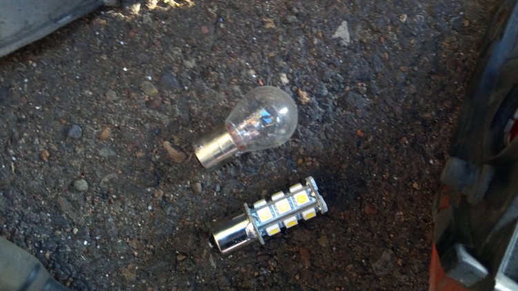
This is a good comparison between a normal bulb and an LED bulb.
I am very happy with the results. The LED bulbs respond almost instantaneously rather than slowly like the incandescent bulbs do. The full conversion was a little more involved than I had anticipated but it all worked out in the end. A few notes for those who are doing this conversion: Be sure to replace the stock flasher relay and also the self-cancel module. Be sure to install the relay as I did on top of the automotive replacement relay. Otherwise you will have voltage on the harness on either the Lb or O wires. Check the IPCRC for more information on the trouble-shooting process I went through.
When I get a chance, I will take some photos of the bike’s lights during the daytime and at night so that you can see what it looks like with the new lights.


Did you have to replace the self-cancelling unit due to the LED swap in the cluster or on all four sides?
I reads like the cluster LEDs would cause the problem, but I find that hard to believe.
Thanks for adding the information!
Hi Sefan!
Yes, I did replace the self-canceling unit in the LED swap. However, you don’t have to. You can put resistors in series with the LEDs to mimic the same load the stock self-canceling system would see with incandescent bulbs. If you don’t do that, the self-canceling unit will burn itself out. The internal workings of the self-canceling unit expect to see a certain amount of current and resistance. The LEDs alone don’t supply that. With resistors only on the circuits that activate when the turn signal is on, the self-canceling unit will remain happy. Otherwise you’ll have to replace the unit like I did and lose the self-canceling abilities.
One of these days I’ll reinstall another self-canceling unit I picked up a while back and add resistors so that I get my precious self-canceling turn signals back again.
Cheers!
Douglas
Hi Douglas,
THanks for the reply! At the moment, I’m thinking o only converting the little wedge bulbs to LED, not the real signal bulbs. Do you still think they need the resistor to maintain the proper load (3.4W)? What kind of resistor did you add?
Talking about resistors, they you by chance know to best plate to add the resistor for the corrected fuel gauge reading? I thought I could add the resistor in the instrument cluster, too. That one has to go in in parallel, but not sure which cables to connect.
Thanks,
Stefan
Hi Stefan,
I think you can convert the bulbs in the dash without too much trouble although I didn’t test that configuration with the self-canceling turn signal module. You would need to see how many watts the LEDs consume and then find a resistor that consumes the difference in watts. It should be small enough though that it won’t matter.
There is probably a place you could add a resistor to the fuel gauge in the cluster. Otherwise if you buy the O-ring, the preferred method is to remove the fuel level sensor in the tank and bend the float arm to suit your desired measurements. Have the tank below “E” on the uncalibrated gauge display when you remove the fuel level sensor. I’d say that it’s actually easier to do this than to cut a wire and add a resistor.
Cheers!
Douglas
No wire cutting is necessary in the resistor mod for the fuel gauge. You just poke the resistor legs into the socket. Wrap some insulating tape around it to keep it secure.
Hi,
my name is Albert.
I have undertaken a full LED conversion and am pleased with the added brightness in the dashboard and other signal lights. I will probably add some additional LED strips, in appropriate colors, around the body for additional nighttime visibility.
The only question remaining is with regards to the self canceling circuitry.
I replaced the turn signals and dash indicators with these: https://www.amazon.com/gp/product/B019O2SI5I/ref=oh_aui_detailpage_o02_s00?ie=UTF8&psc=1 (link to amazon)
and these: https://www.amazon.com/gp/product/B018Z5RU36/ref=oh_aui_detailpage_o01_s00?ie=UTF8&psc=1
SO: where as the original turn signals, when flashing, would consume (27w x 2) + 5w = 59 watts (2 1157s + 1 t10)…
The new configuration consumes: (15W x2) + guessing about 1 watt for t10 ~~ 31 Watts
Summing it up old (59 watts) vs. new (~31 watts).
Question: is 31 watts consumption enough to preserve (not fry) the self canceling flasher unit or do I need to add load resistors to make up the 28 watts?
the way I see it the power difference is a burnt out bulb. I assume the circuit can handle a burnt out bulb without committing Seppuku https://en.wikipedia.org/wiki/Seppuku
And if I need to add resistors is it enough to add to just one ‘bulb’ on each side OR does the flasher require that the load be balanced across front and back?
P = V * I
28 = 12 * 2.3
V = I * R
12 = 2.3 * R
R = 5.21
Hi Albert,
The best that I can say is that I really don’t know the consequences of doing what you propose. Probably it will be fine but there is the possibility that there is some other property of the LED setup that caused my turn signal cancel computer to burn out. If you’re ready to buy a replacement off E-Bay if the unit does burn out, I’d say to go ahead and test your theory.
Good luck and please let me know how it goes!
Douglas
Ain’t nuttin’ like trail by fire…
How long did it take till the unit fried in you particular case?
I think it took all of 30 seconds to fry. This was a number of years ago though so my memory is not perfect. It was definitely under a minute of blinking.
In that case i am past the moment of terror and going forward into the unknown… I will update in a few days.
Thanks.
Just a follow up.
After a few weeks of riding with the LEDs installed I can report that the self canceling unit is unaffected… for now…
Thanks for all the info you share.
Albert.
Did this conversion hold up? I’m looking to do the same thing this winter and would rather not mess with adding the resistors if I don’t have too. Thanks
Yes. I ran with it all season with no problems. I purchased the leds on ebay (i think jt was led king).
The only annoyance was that everyone sells headlights in pairs .
It is nice to actually see the dash lights in daylight!
I ended up doing the full conversion this weekend. I replaced the flasher relay but I still had to add 25w resistors to the turn signal indicator bulbs in the dash. When I tried it without the resistors all of the turn signal bulbs were very dimly lit all of the time.
I ended up having to do some trickery with relays to only allow electricity to go to the bulbs when the flasher was running. Otherwise, I’d have the same thing where the bulbs were dimly lit when they weren’t being used.
I purchased the direct t10 replacements. They probably had the ballast built in.
Yup they probably do. Do you like those lights?
Thanks for posting this information! I have a 1998 Pacific Coast, which didn’t come with a flasher or turn signal cancellation. If I wanted to replace the turn signal, running light, and brake light bulbs, would a simple swap be all I need? Also, is it possible to replace the headlight bulb with an LED, or would that require replacing the entire reflector? Thanks for posting this information!
Hi Jim!
I’m a little confused by your bike’s setup. Are you saying that you have no turn signals at all? Or did a previous owner bypass the turn signal self canceling system? It’s also possible the wire that goes between the speedometer and the self canceling unit got broken which would mimic not having the self canceling unit. If the self canceling unit has been removed, then you could swap in the LED bulbs without problems (assuming you’re also putting in a new flasher). However I’d be pretty surprised if that’s all you would need to do. The easiest way to do it would be to add in some resistors with the turn signal LED bulbs so that you don’t have to replace the flasher or worry about if your self canceling unit is there or not.
Cheers!
Douglas
The last few years of PCs were somewhat “decontented.” They had turn signals, of course, but they were not self-cancelling (they also had a simple front fender identical to the one on the old Nighthawk).
Hi Douglas,
Due to your information I have replaced my cockpit bulbs with LED, and my front and rear lights also.
I am very happy with the result but now I am not sure if I am capable to do a LED conversion of my turn signals, I am not that good with electronics so that is why. Do you think that this conversion is possible for someone without electrical experience?
Hi Raymond,
It would help if you have some experience with soldering and with a multi-meter. The easiest way to do the turn signal LED conversion is to use load balancing resistors. A lot of auto parts stores sell them. But you have to solder them in with the wires that go to the turn signals.
There might be a mechanic near you that could do the work for not too much money. It should take someone who knows what they are doing maybe two hours to do the work.
Lots of info and options here and I’m a bit overwhelmed. I’m doing a LED running lights (not dash) conversion on my ’89. My question is if I use 50w LED load resistors (RL-650 from superbrightleds.com) at each turn signal bulb will the stock flasher and auto-cancel work correctly? I thought that just replacing the flasher would be an easier option but I didn’t think about the auto-cancel. Thanks for being here, Doug. You’re a treasure for us newbies.
Jeff
Hey Jeff! Happy that you’re finding all this info and lessons learned from my own mistakes to be useful 🙂
I think that those resistors should be about right. But you can determine this yourself by looking at how many watts in total are used by the LED bulbs and compare that to the incandescent bulbs (on each corner of the bike plus the ones on the indicators in the dash). I think the difference is probably around 50 watts? Can’t recall off the top of my head. But that’s how I’d go about sizing them. If you have too many watts on your load resistors, I’m not sure what will happen. Maybe a blown fuse or maybe the flasher will blink very slowly. If it’s too few watts on the load resistors, the flasher will blink real fast followed shortly by the computer burning out.
I actually have a second computer in my spare parts that I really need to get around to installing on my bike… I miss having self-canceling turn signals some days.
Cheers!
Douglas