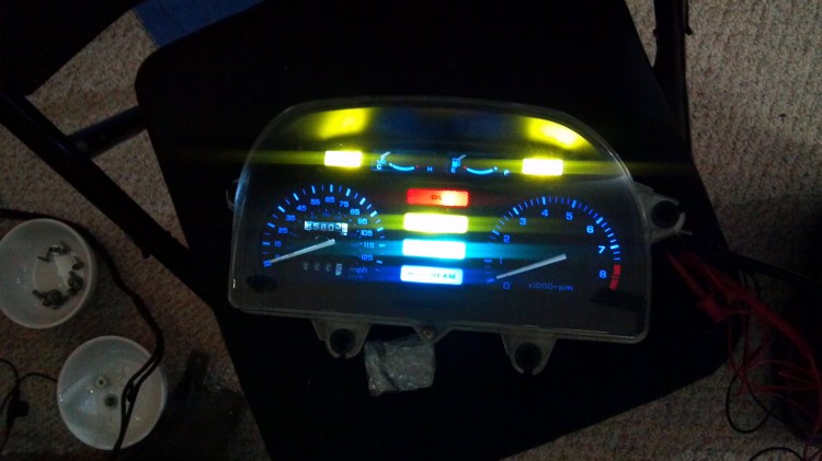
Over the course of the last few months I upgraded my PC800 from incandescent bulbs to 100% LED bulbs. Every single bulb down to the bulb in the Honda Marine Voltmeter has been changed out for an LED replacement. The full list of bulbs I purchased is available here. Above you can see all of the bulbs in the meter panel lit up. The bulbs I selected wash out the blue and green colors for the neutral and high beam lights but do well everywhere else. It’s not a big deal to me but some people might want to color match LEDs to the various lens colors.
I ended up replacing the self-cancel turn signal unit on my PC800 with some relays to disable self-cancel functionality. Eventually I want to build my own self-cancel unit either based upon an Arduino or done through circuit design. It might take a few months but I’ll eventually get full turn signal cancel functionality back. If you are doing an LED conversion, I would suggest bypassing your self-cancel unit so that you don’t let the magic smoke out. I made that mistake which is why I ended up having to bypass my (dead) self-cancel unit.
I also replaced the flasher relay in my PC800. Initially I built my own but then I found an off-the-shelf unit that I liked better. Unless you like building your own electronics, I would suggest buying the off-the-shelf unit. It is much simpler.
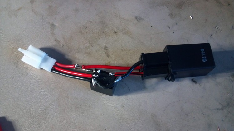
I modified the off-the-shelf flasher unit with a relay (seen above) to disconnect the load leg of the relay from the rest of the bike when I am not using the turn signals. This is to prevent leakage current/voltage from getting into the rest of the wiring harness and causing very dim but still visible lighting of the turn signal indicators even when they aren’t in use. The load lead is hooked to the Normally Open side of the relay. One side of the relay coil hooks to the +12 leg and the other hooks to the ground leg. Note that the ground leg goes to +12 when the flashers are not in use thus deactivating the relay. The diode that you can see above isn’t strictly necessary to the circuit but I decided to put it in anyway. It goes with the white stripe toward the ground side of the circuit. Easy!
This is a schematic drawing of the circuit that I used to disconnect the load leg of the relay. Yes, it’s a bit primitive of a drawing but you should be able to get the idea.
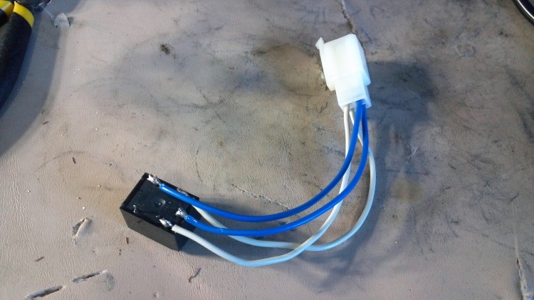
I also decided to replace the position light relay while I was at it. The two white wires go to the coil and the two blue wires go to the normally open part of the relay. There isn’t any reason to replace this relay but I decided to do it anyway. The Honda part number is P/N: 38601-MB3-671. Rather than pay $35-$45 for a replacement, you can build your own for under $15. If anyone wants ore details, I can look for the schematic I drew of this circuit and post pictures. Just leave a comment below and I will put it up.
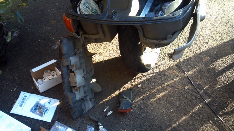
I swapped in the LED bulbs throughout the bike. They are very easy to install.
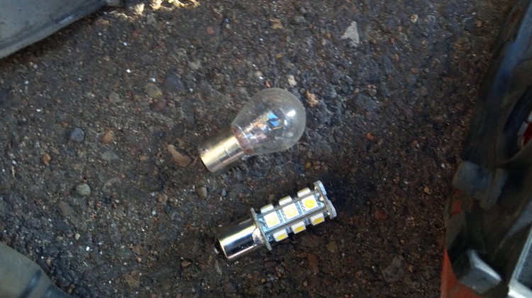
This is a good comparison between a normal bulb and an LED bulb.
I am very happy with the results. The LED bulbs respond almost instantaneously rather than slowly like the incandescent bulbs do. The full conversion was a little more involved than I had anticipated but it all worked out in the end. A few notes for those who are doing this conversion: Be sure to replace the stock flasher relay and also the self-cancel module. Be sure to install the relay as I did on top of the automotive replacement relay. Otherwise you will have voltage on the harness on either the Lb or O wires. Check the IPCRC for more information on the trouble-shooting process I went through.
When I get a chance, I will take some photos of the bike’s lights during the daytime and at night so that you can see what it looks like with the new lights.

