Note: The original post has been updated to fix some factual errors with the gracious help of a now-retired employee of the Goldstone complex.
On Friday three other JPL interns and I set out for the Goldstone Deep Space Communications Complex which is housed on the southwest edge of Fort Irwin, a military base near Barstow, California. It is also very near to the China Lake Bombing Range. We were lucky enough to be given a VIP tour of the facility including the massive 70 meter antenna, several historic antennas, a land shark, the control room where we got to press some buttons, and the receiving and transmission room of the most advanced deep space transmission research complex in the world. This trip was every nerd’s dream come true!
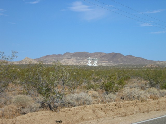
The twin Gemini antennas (DSS 27 & 28). These were built for the Department of Defense back in the early 90s to study low earth orbit satellite communications. Later the dishes were transferred over to NASA. Some people and sites will inform you that the Gemini were built for the StarWars program in the 80s however this is not true.

Goldstone has a problem with burros. We saw several on the ridge line above the 70 meter Mars antenna (DSS 14). The guards at the front gate told us that the burros are trapped in the facility by a fence that the military erected a year or two ago. From our visit, I can confirm that there definitely is a fence where Goldstone land borders the military base. However I am not sure if there in fact is a fence on the BLM-Goldstone boundary. I suspect that if there is not, natural barriers such as mountains and distance to the next water source keep the burros from leaving.
The burros really enjoy tearing up the sparse vegetation around some of the buildings and gnawing on sprinkler heads to get at the water in the pipes. NASA now pays for hay and water to keep the burros away from its buildings. That might be another good reason for the burros to stay.
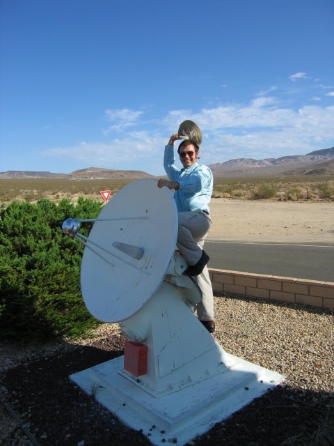
The front gate had several of these antennas installed as artwork. I decided that they needed to be ridden. Major Kong would be proud.
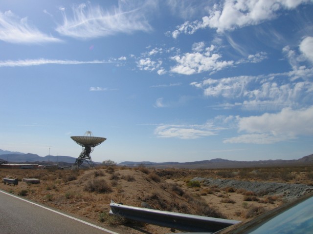
Echo antenna (DSS 12). This decommissioned antenna is now operated by the Lewis Center for Educational Research as a tool to get grade school through high school students interested in science. Students from around the world get to remotely control the antenna to conduct observations of various stellar phenomena. The data they collect is processed and included in a NASA database. Several years back the students discovered a new radiation belt or two around Jupiter.

Another shot of the Echo antenna. It is one of the earliest antennas on the Goldstone site. Had the Lewis Center not stepped in when it did, another newer and larger antenna would be located here instead. That newer antenna was built elsewhere on the site.

The little public museum at Goldstone has some fun space memorabilia in it. This is one of the front landing gear tires from the Space Shuttle. All of us had to sit in it for a picture.
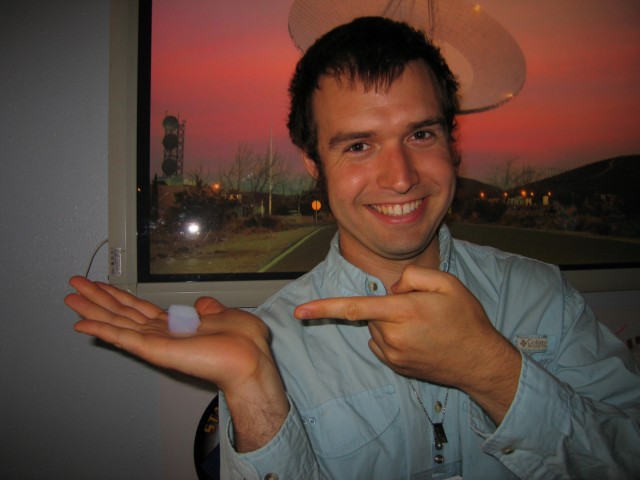
That opaque cube in my hand is aerogel. It’s the lightest solid known to man. There were a couple of blocks in the museum that the tour guide let us play with.

This is inside a lab that maintains RF signal boosting equipment necessary for spacecraft communications. The two blocks of copper on the front of the cart are mechanical RF amplifiers. The odd looking tower with the gold foil on the back of the cart is an assembled mechanical RF amplifier known as a Microwave Amplification by Stimulated Emission of Radiation (MASER).

This is an electrical RF amplifier that is designed to someday replace the mechanical amps. The mechanical amplifiers still outperform the electrical ones, however.
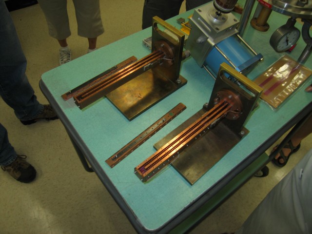
Inside the mechanical amps are a series of copper comb structures and ruby rods. The rods look sort of like very expensive rulers that one might use in elementary school. Yes, NASA made rods out of rubies to amplify signals. And not just any rubies. These were specially grown and manufactured in a lab with a doping agent that turns the rubies into signal amplifiers. The ruby rods are about 1/8″-1/4″ thick by 1/2″-3/4″ wide by 4″-5″ long.

The motor thing in the middle of the table is a cryo pump that achieves 15 Kelvin at its tip. It gets shoved up inside the middle of the tower contraption. Liquid helium run through a throttle valve develops a 4 Kelvin region that cools the amplifiers down to their working temperatures. The amps (both mechanical and electrical) boost signals that are one trillionth of three billionths of a Watt (specifically -175 dBm which is equal to 3.16 * 10^-21 Watts) to something usable by commercial signal processing equipment.

We drove on to Apollo Valley where DSS 16, DSS 17, DSS 24, DSS 25, and DSS 26 are all located. DSS 17 was for shuttle and other low earth orbit tracking missions but when we visited it had its power cables cut, and most of its internal equipment removed for about a decade. It could move rapidly across the sky to track an object but is a smaller dish (9 meters) and thus couldn’t hear the distant deep space calls of some of our spacecraft. Since my visit to Goldstone, DSS 17 has been dismantled and removed.
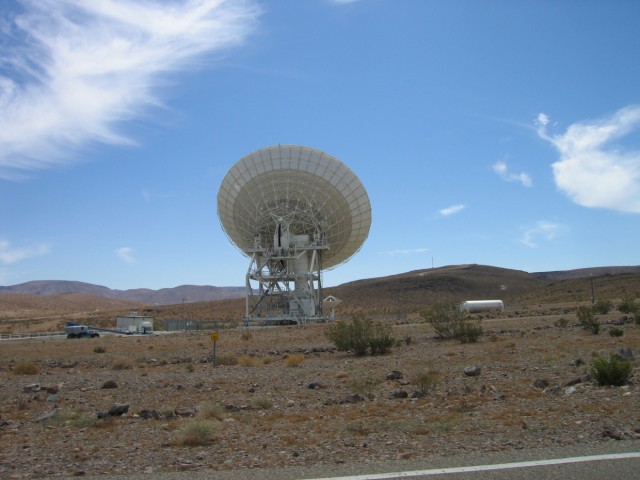
The backside of one of the antennas in the Apollo antenna complex. Note the “baby” antenna next to it. It is used for other observations not related to communicating with the deep space satellites.
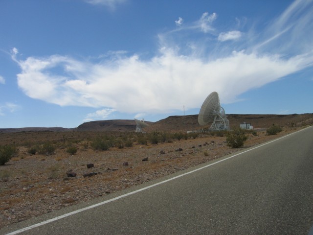
A couple of the antennas in the Apollo complex. Each antenna complex was located behind a hill such as the one in the background to reduce radio interference from populated areas to the west and the military base to the east.
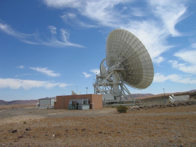
A typical antenna setup. The antenna is anchored by a massive multi-story underground concrete block. The building next to it houses cooling and power equipment. Signal processing for all antennas except DSS 12 and DSS 13 is handled by another facility (SPC-10) located next to DSS 14. Photos of that facility are later on in this post.
Underneath the telescope is the room where the signal is received and amplified. Signals are also broadcast from this room. Near the end of this series of photos are several pictures inside one of those rooms.
On the older dishes the signal receiving and amplification is done way out at the end of the focal point or up in the antenna. The technicians and engineers don’t like these types of configurations because it takes much more time to fix problems.
The very small antennas next to the larger antenna are used to measure atmospheric water vapor (they are called Water Vapor Radiometers) during Very Long Baseline Interferometry (VLBI) measurements.
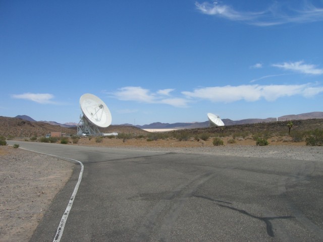
Looking back toward the other antennas in the Apollo valley. Off to the right the cone from DSS 16 is just barely visible poking over the hill.
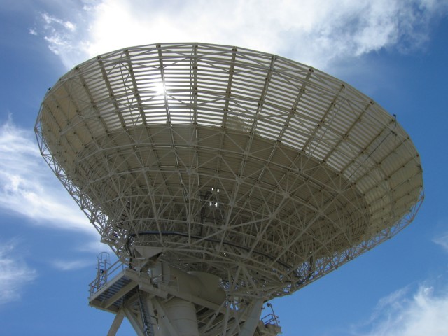
This antenna (DSS 24 or 25 or 26) is only 34 meters across. It’s small compared to the largest antenna at Goldstone.

The base is massive. A track and some huge wheels allow the entire structure to rotate. Each wheel weighs about two tons (imperial).
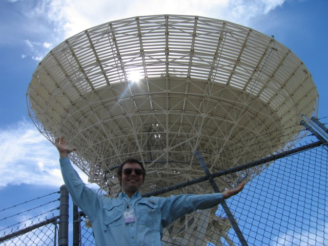
I can almost span the dish with my arms. That’s because I’m a huge giant. Note my sweet JPL badge. Having government issued photo ID gets you all sorts of perks!

The dish in all its glory. That is an 8 or 10 foot tall fence about 100 feet from the base of the antenna. In other words, it’s HUGE.
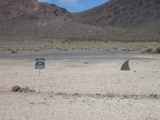
The workers out at Goldstone sometimes get a little bored and lonely. They decided that the shark mudflats needed a warning sign.
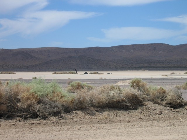
The Goldstone Dry Lake has a monster. I am told that for a few weeks every year the alkali lake bed fills with water making the monster even more of a sight to behold. Nearby is the airstrip where an experimental UAV from Canada was being tested.
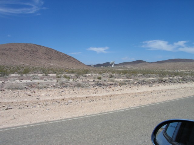
The Mars (right, DSS 14) and Uranus (left, DSS 15) antennas off in the distance. It’s 14 miles from the entrance of Goldstone to those two antennas. This is a really big place.

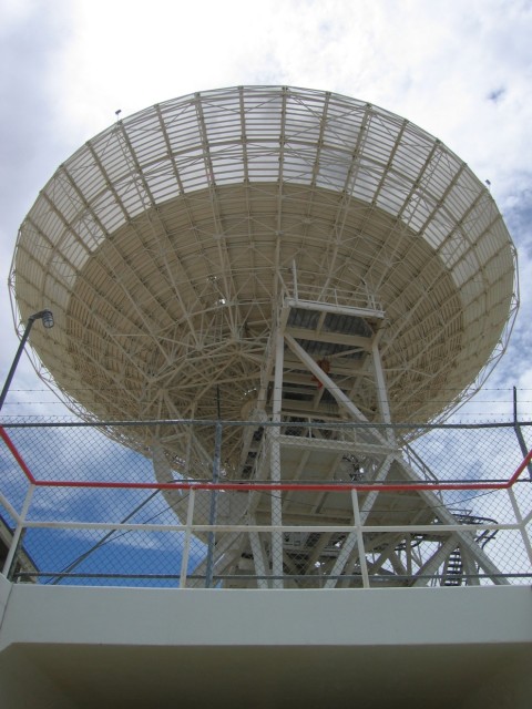
The biggest antenna on site. It’s a mere 70 meters across. That equates to about an acre of surface area. This was a prototype antenna, the first time using hydrostatic bearings on such a large and accurate scale. Originally the antenna was 64 meters across. In the 80s it was upgraded to 70 meters.
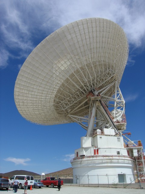
The little orange lines running up the side of the telescope are ladders and catwalks. It is very difficult to understand just how massive this telescope is until you stand at its base. Our cars are parked next to the perimeter fence for the dish. We are technically outside of the zone directly under the dish but when we looked what felt like straight up it sure looked like it was directly overhead.

While Goldstone is connected to the grid, it also has enough diesel generators to power the entire place. It was a hot day in California when we visited. The power company had asked Goldstone to shed some of its load and run a few of the generators. These generators had been operational since the DSS 14 site was built. Other generator banks are scattered throughout the Goldstone complex at the various antenna sites.

Inside the main signal processing facility for Goldstone. We were allowed to walk around and through the equipment as long as we didn’t touch anything. The braces above the racks are to prevent the rack from toppling over during an earthquake (the Garlock fault runs not far from this location). The brass colored circles you see on some of the floor tiles are locking mechanisms to keep all the tiles together, thereby keeping any from falling into the basement if the floor shifts during an earthquake.

I couldn’t resist the temptation. If a mission is lost in the near future, this might have been why.
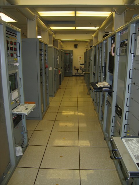
Row upon row upon row of signal processing and recording equipment. It was the size of a small data center and with computational power to match. There were also plenty of very old school instruments, too.
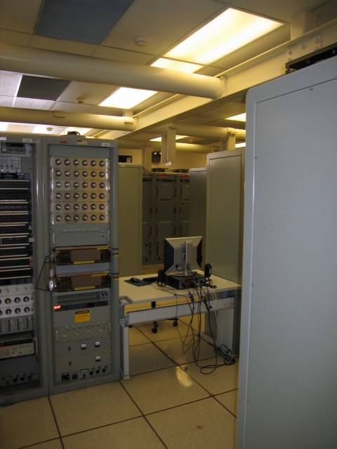
I really hope this place comes with an instruction manual. Otherwise no one would ever know what all those knobs do and what value they should be set to.
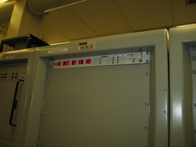
A display for one of the multiple atomic clocks at the facility (kept in the basement). They are precisely synced with the other DSN facilities in Australia and Spain to provide precise timekeeping. It’s necessary when dealing with spacecraft many millions of miles away.

Some control panels either being thrown out or getting ready to replace current equipment. All of the control stations (see below) are being upgraded so that each operator can run multiple antennas from one seat.

All of the cables were labeled but the dongles were not. Sometimes you have to wonder what would happen if the guy who knew what cable did what retired.
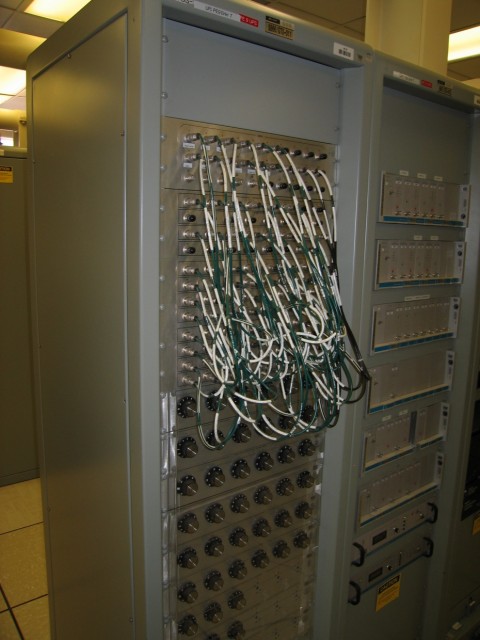
The internet: a series of coaxial cables and knobs.
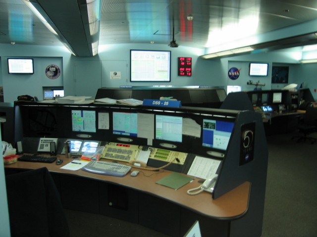
Looking into the control room. There were six or so control stations and a twin supervisor desk.

One of the operators doing his thing. The whole place runs on Unix. Very old technology, such as the push button panel and the yellow “telephone”, has been married with very new technology. The telephone is actually an intercom system to talk with the rest of the facility, announce things over the PA speakers by the dishes, and talk with the various spacecraft mission control facilities that are responsible for all of NASA’s satellites. In many places these intercoms are actually headsets. Here they still use telephone handsets for comfort. I’m told it’s not fun having a headset strapped to your head for eight hours straight.
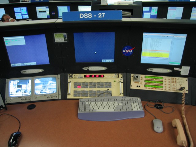
The panel in the middle switches between different antennas and indicates if the antennas are receiving or transmitting or offline. The video monitors to the right can show an oscilloscope somewhere either in the signal processing center or at the antenna and an external shot of the dish to make sure it’s really moving and functioning properly.

It has to be a tad bit overwhelming if it’s your first day on the job to manage all of those monitors. Each one has important information displayed on it. And each one can have multiple desktops brought up displaying very different and equally important information.
The guy running this station was the last person to communicate with the Galileo spacecraft before it plunged into the Jupiter atmosphere. Before he worked at Goldstone he was in the Marines doing satellite communications work for 20 years. He was gracious enough to talk with us for about 20 minutes and let one of my friends talk with mission control back at JPL who were controlling the DAWN spacecraft during our visit.
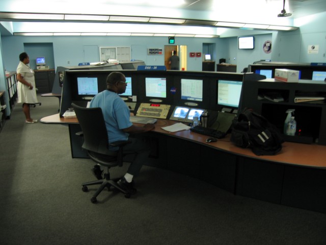
This guy has been working at the facility tracking spacecraft since the Apollo era. He works five days a week as an antenna controller. If he ever retires a lot of the knowledge and history of the place will leave.

The Echo (DSS 12) antenna from the main road.

Above the engineering buildings and cafeteria, someone spelled out GOLDSTONE with whitewashed rocks. Echo antenna (DSS 12) is off to the right.

The friendly guard at the gate. He and his fellow guard were pretty lonely. When we arrived we spent 10 or 15 minutes talking with them while we waited for our tour leader to arrive. As we were leaving he wanted to know why we hadn’t taken a photo of him. All four of us took a photo.
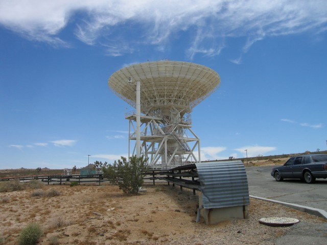
The Venus (DSS 13) antenna. Not very many people get to go to this antenna. It’s a research and development center where the next generation of receiving and transmitting equipment are tested.


We were lucky enough to be given a tour of the amplification, receiving, and transmitting room underneath the telescope.

The big reflector dish in the middle of the room takes the signal that is beamed down from the antenna and sends it to whichever instrument is being tested. This is the only telescope at Goldstone that is outfitted with a rotating reflector dish. This allows up to six instrument suites to be tested by simply rotating the RF ellipsoidal mirror from one position to the next.

The big tube is where the signal is beamed down from the antenna above.


Yes, that is a NASA garage door opener. The previous device that was custom-made to deploy and retract the foam cover over the receiving horn was very unreliable. The engineers at Goldstone replaced it with a commercial garage door opener and haven’t had a problem since.
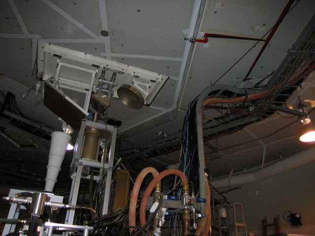
The red tubes are feeding a coolant similar to what we use in our cars to cool the transmitter.
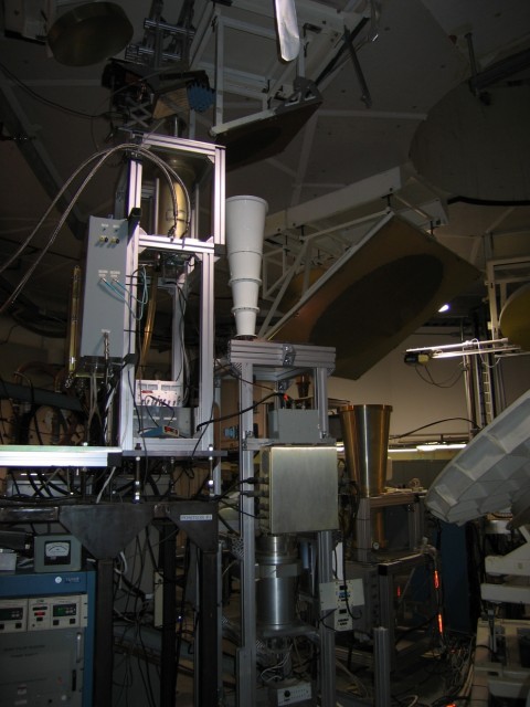
The white horn is an X-band receiver while the very small horn above and to the left of the white horn receives KA-band transmissions. The big horn to the right probably receives either S-band or X-band. In the last ten or so years most deep space spacecraft have moved to X or Ka-band transmissions and away from S-band. The S-band segment dedicated to spacecraft communications is fairly full with current NASA missions including many that are not classified as “deep space.” At Goldstone there is also a fair amount of pollution on the S-band due to weapons system and aircraft testing at Edwards Air Force Base and China Lake. X and Ka-bands also achieve much higher data rates.
The two metal tubes running into the shiny gold-colored device (a MASER) carry ultra-pure helium to cool the MASER to its optimal working temperature.
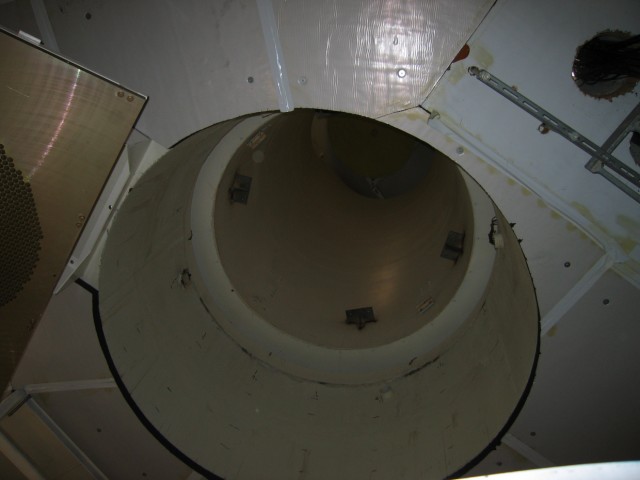
Looking up the massive tube that runs up to the antenna. It is open to the outside world and has been a favorite location for birds to get themselves in trouble. When we arrived at the site, the bird sirens were going off trying to scare the birds away. The birds were still flying around the dish. They didn’t care.
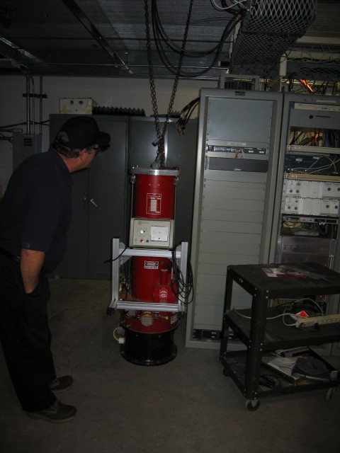
An experimental transmitter designed and built by Stanford. Notice the Stanford cardinal red color. I am told however that all all transmitter power amplifier tubes are painted that color to denote “RF radiation warning.” Maybe this is why my university doesn’t do research in that area. If it can’t be painted orange and black, Oregon State won’t do it!

Walking back out of the underground antenna bunker. It was about 23 C in the room while outside it was at or above 40 C.

The sign welcoming everyone to Goldstone. Personally I think that the logo looks an awful lot like the StarTrek emblem. The others in our group were a little more skeptical of this interpretation. As a side note, “laboratory” was spelled incorrectly when the sign was first erected. It took several months for the sign to be corrected.
NOTE: Special thanks to Ralph M for helping to correct the errors from the original post. If you see a factual error, please contact me and let me know!

typo in post: “of it’s load” should be “off its load”
Which “of it’s load” do you mean? Both instances I could find I think are correct usages.
And that was a totally sweet tour. Thanks for organizing this!
I was searching for Goldstone and Deep Space Network and this came up. Thought it was funny that the first two pictures looked so familiar, then I saw the third… Thanks as well for organizing the tour.
Wooo! My Goldstone post has relevance on the intertubes!
This is stunning Doug! Keep up the awesome!
Thanks Kosta! Come back to LA and I’ll take you out for your own personal tour!
Impressive man!
Do you know if they allow a foreign like me (Brazilian) to have this tour or a similar one?
Hi Joabel,
I don’t know what the restrictions are these days. Your best option is to contact the people at Goldstone to ask. When I contacted them, they were extremely nice and happy that we came out to visit.
Cheers!
Douglas
Thank you Douglas, I’ll do that.
Tks
No problem! Let me know what you think if you manage to get out to Goldstone. It is a really neat place! 🙂
As a past Station Director at Goldstone in the 80’s and 90’s, I enjoyed your commenets.
Brought back some very fond memories of the early frontier days of spacecraft tracking.
Hi Jay,
I’m happy that my photos and descriptions could bring back some happy memories for you. Goldstone is a truly magical place. A friend who is an operator and scientist at Arecibo Observatory just gave a presentation in my department last week about radar imaging that Arecibo and Goldstone both can do. Really fascinating stuff!
Cheers
Douglas
Jay, I don’t know if you aware or not, but you are featured on this BBC video
Alan