Editor’s Note: I have copied this information over from the files section of the iPCRC. I have edited a tiny bit for clarity. Unfortunately it appears that the images associated with the original post have been lost to Yahoo’s file management system. However, some may find this information useful.
OK Guys, here’s my step by step.
This procedure assumes that you have already removed the maintenance covers(left side), side panels(left side), the top shelter(may not be necessary), and the seat. The repairs done on this bike are applicable to the 90-98 model PC’s and may or may not need some small changes for the 89 model at the regulator.
BEFORE STARTING THIS MOD, DISCONNECT THE NEGATIVE BATTERY CABLE FROM THE BATTERY.
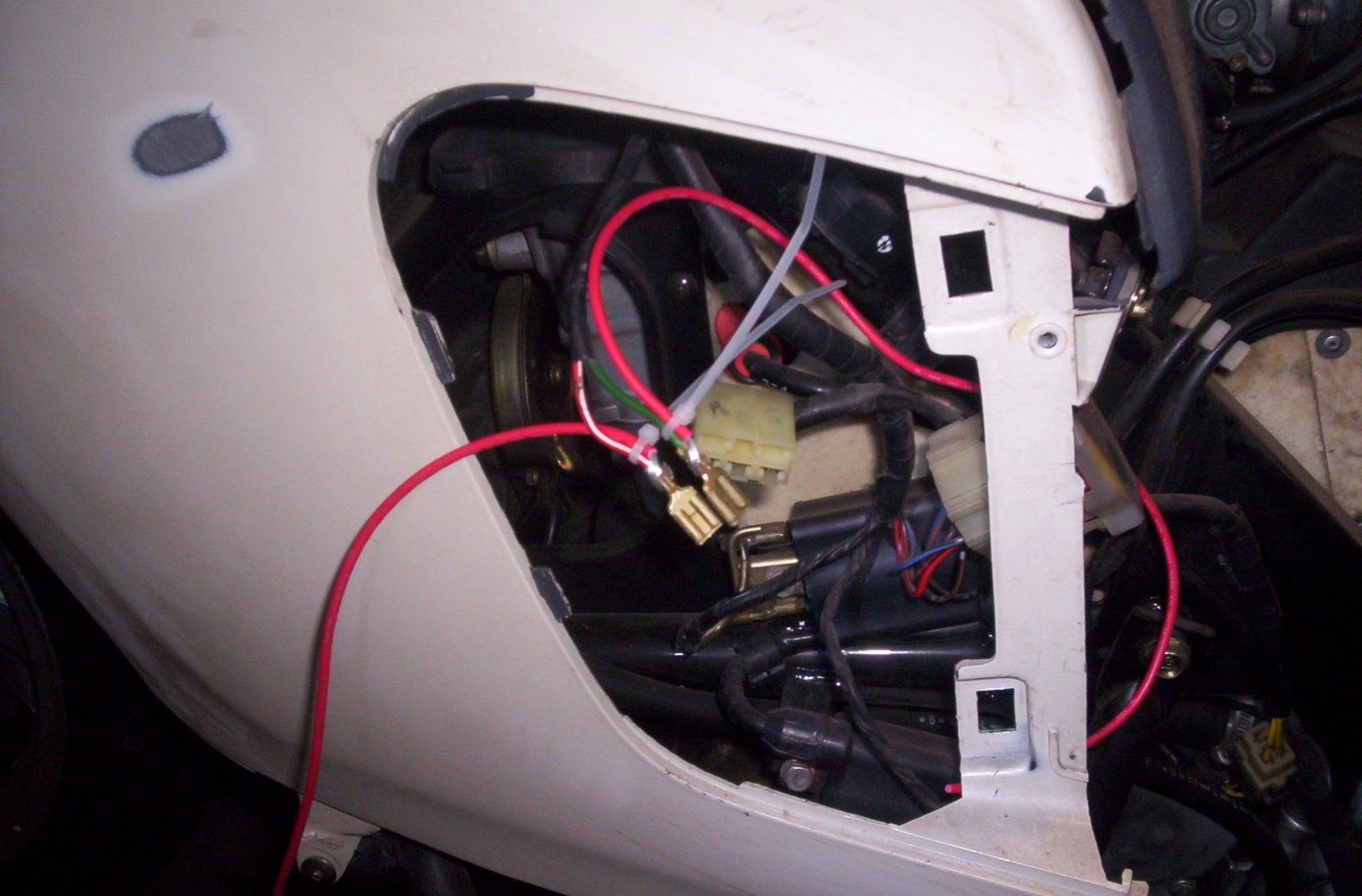
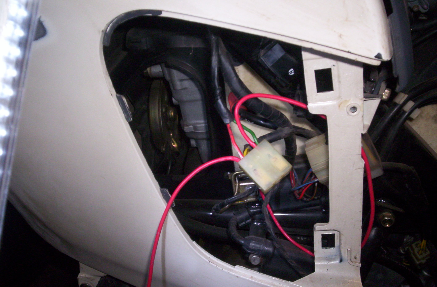
1) Open the wire loom holder which holds the wiring harness located in front of the regulator/rectifier (R/R).
2) Unplug the connector from the R/R.
3) Mark connector for the location of the Red w/white tracer(positive) and Green(ground)wires.
4) Carefully unplug the wires from the connector – tab retainer is part of the plastic connector, not part of the wire terminals.
5) Strip back wire ends of wire(16-14ga) to be used for this mod. Wrap bare wires around the base of the wire terminals and secure in place to prepare for soldering. Illustration #1
6) Solder new wires to terminals and let cool before handling. (To protect your the electronics on your bike, use a heated tip soldering pencil not a resistance type soldering gun.)
7) Re-insert wires into Connector. Illustration #2
8) Re-insert connector into R/R.
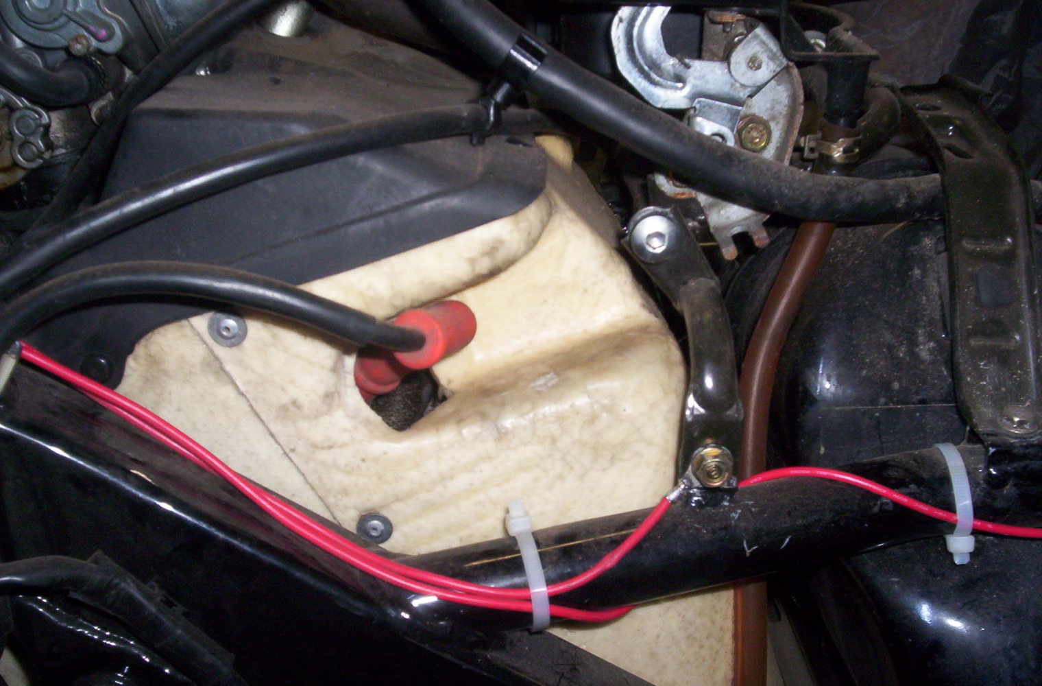
9) Route ground wire to nearby grounding location. Cut wire to length and solder eyelet to the end of it and let it cool.
10) Attach ground wire to frame location. Illustration #3
11) Re-insert wires into wire loom in front of R/R and close holder.
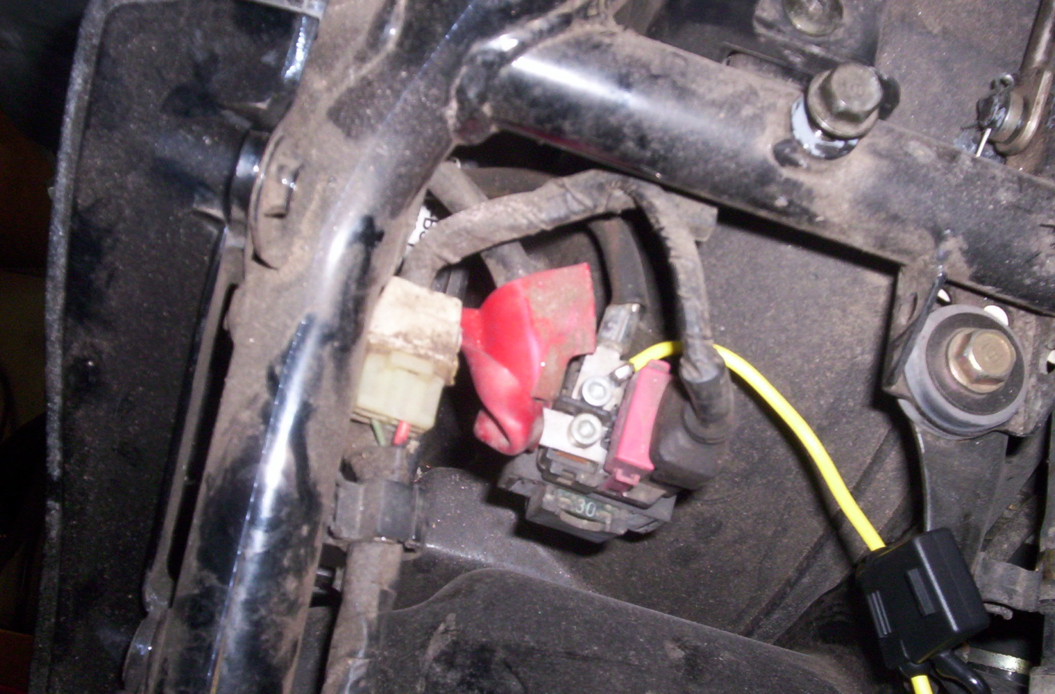
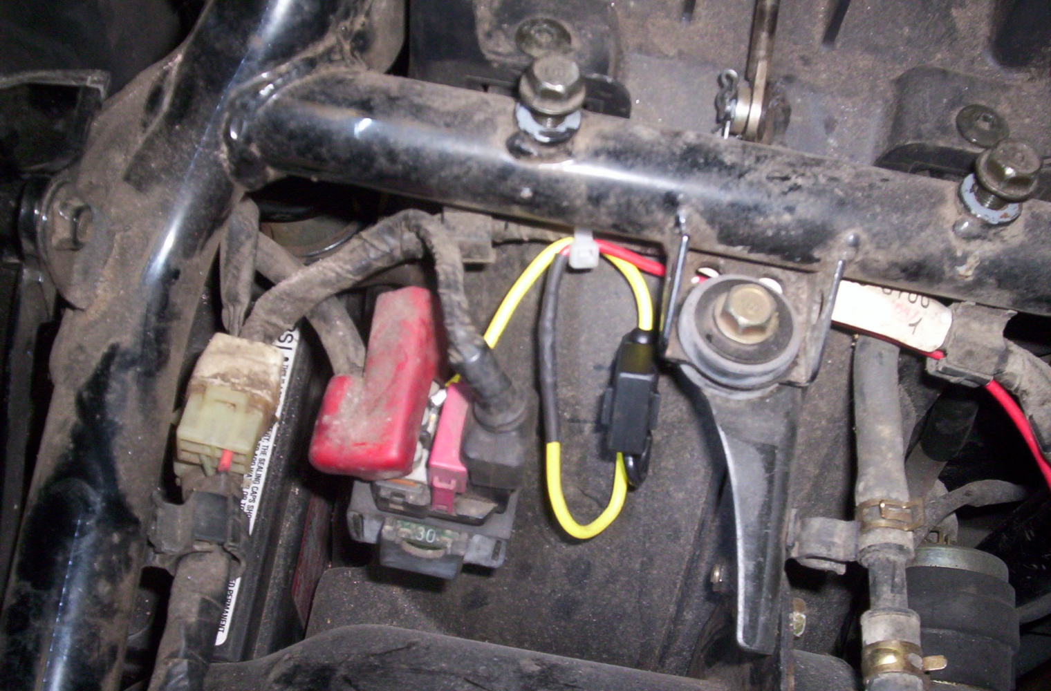
12) Solder eyelet to wire end of fuse holder and connect to the battery side of the starter relay. Illustration #4
13) Route positive wire from the R/R to the fuse holder and connect and solder. If using heat shrink to seal and insulate the connection, remember to slip the heat shrink over the wires before you solder the connection. Otherwise, after the connector has cooled, wrap the connection with black tape.
14) Arrange new wiring so that it won’t rub through on any sharp edges or get pinched by the seat when you re-install it. Secure wiring as needed with cable ties. Illustration #5
15) Install 15 Amp fuse and re-assemble your bike.
This procedure has worked well for me.
As always, perform this procedure at your own risk.
If you’re not comfortable with the level of skill needed to complete this don’t do it.
John Handford, literidr@…
Taylors, SC
’90 PC “Spirit”
’94 PC “Chance”